
|
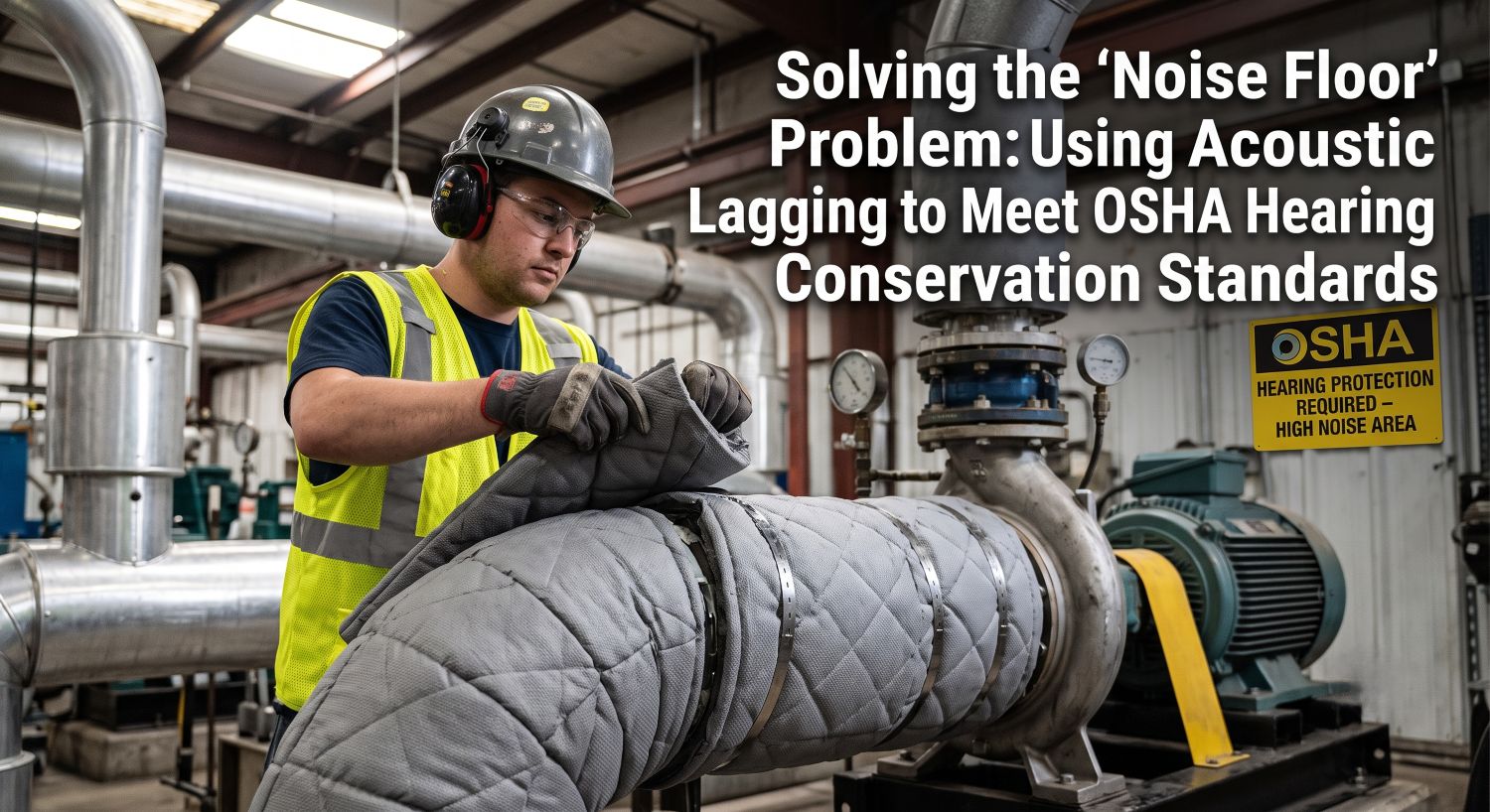
The short answer. The "noise floor" is the baseline sound level a facility cannot get below no matter how many individual machines it quiets, because reverberant energy from every remaining source keeps rebuilding it. It is why plants stall at 88–93 dBA and stay locked in a hearing conservation program indefinitely. Acoustic lagging – a decoupled absorber-and-barrier composite wrapped directly onto the noise-radiating surface – attacks the problem where the sound is created rather than where it is heard, which is what 29 CFR 1910.95(b)(1) actually asks employers to do. |
Every plant safety manager knows the pattern. Dosimetry comes back at 92 dBA. The loudest compressor gets replaced. The next round of dosimetry comes back at 91.5 dBA. Budget spent, exposure unchanged, hearing conservation program still running, and the annual audiograms still turning up threshold shifts.
The problem is almost never the one machine. It is the floor underneath all of them.
What is the "noise floor" in an industrial facility?
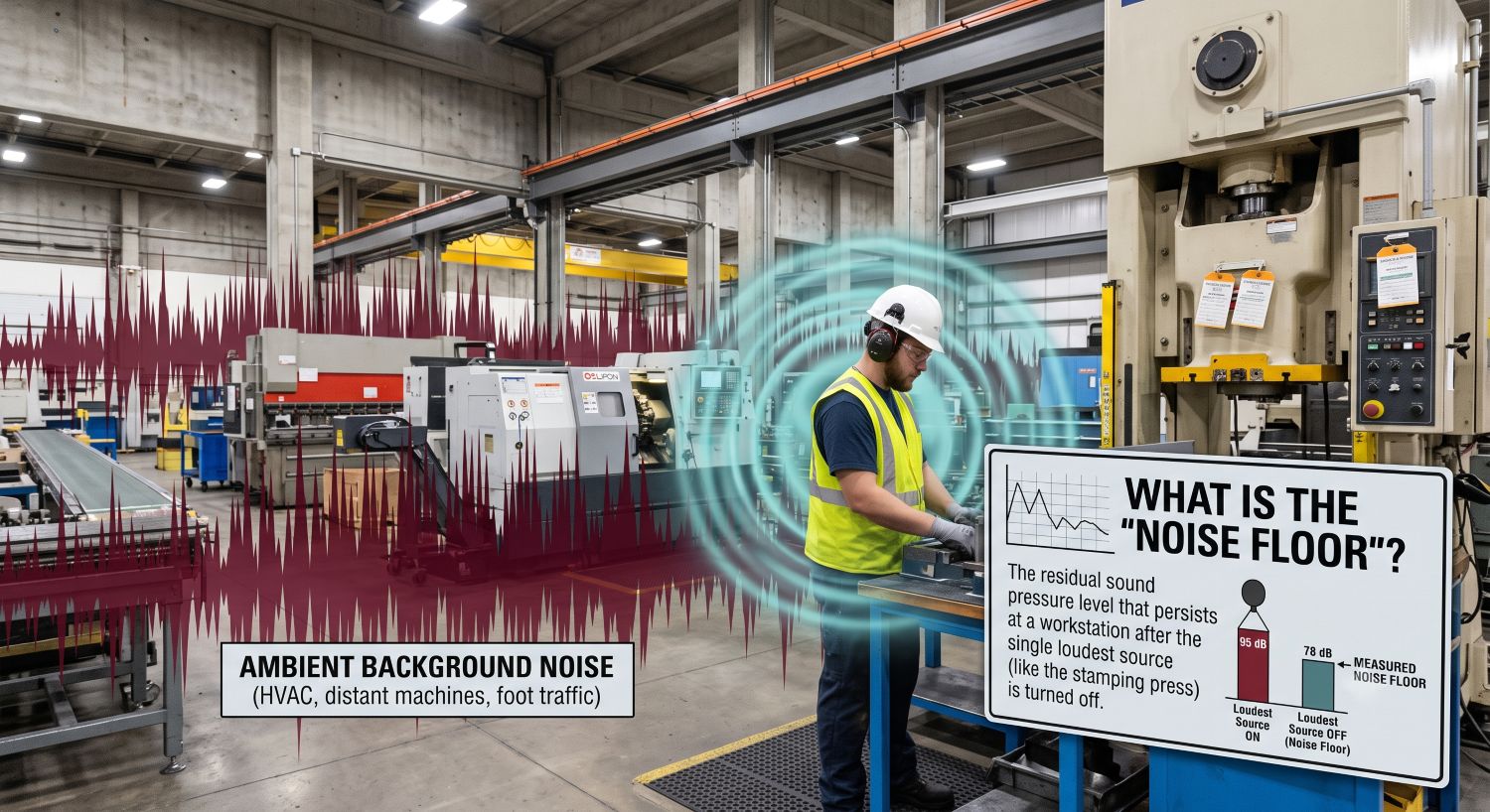
The noise floor is the residual sound pressure level that persists at a workstation after the single loudest source is removed. In a hard-surfaced plant – concrete slab, metal deck, block or steel walls – most of the energy reaching a worker standing 20 or more feet from a machine is reverberant sound reflected off the building, not direct sound arriving straight from the source.
Two pieces of acoustic arithmetic explain why the floor is so stubborn:
- Distance stops helping. Sound from a point source drops roughly 6 dB per doubling of distance – but only in the direct field. Beyond the critical distance, the reverberant field dominates and the level flattens out. Moving the operator station back another 20 feet buys almost nothing.
- Sources add logarithmically. Two equal sources produce +3 dB. Ten equal sources produce +10 dB. Silence one of ten identical machines and the room drops about 0.5 dB.
|
The arithmetic of a failed noise project. Quieting one of ten equivalent sources buys roughly 0.5 dB. Quieting five of ten buys 3 dB. This is the math behind the most common report in industrial noise control: "we replaced the loudest unit and nothing changed." |
What does OSHA actually require when noise exceeds the limit?
OSHA's general industry noise standard, 29 CFR 1910.95, is built on two thresholds and one hierarchy. The permissible exposure limit (PEL) is 90 dBA as an 8-hour time-weighted average. The action level is 85 dBA as an 8-hour TWA. OSHA uses a 5 dB exchange rate, meaning permissible exposure time halves for every 5 dBA increase.
|
Threshold |
Level (8-hr TWA) |
What it triggers |
|---|---|---|
|
Action level |
85 dBA |
Hearing conservation program: exposure monitoring, baseline and annual audiograms, protectors available at no cost, annual training, recordkeeping |
|
PEL |
90 dBA |
Feasible engineering or administrative controls required; hearing protectors mandatory where controls cannot bring exposure within limits |
|
Ceiling |
115 dBA |
No exposure permitted at or above this level (slow response) |
|
Impulse / impact |
140 dB peak SPL |
Never to be exceeded |
Table G-16: permissible daily exposure durations
|
Sound level (dBA, slow response) |
Permitted duration per day |
|---|---|
|
90 |
8 hours |
|
92 |
6 hours |
|
95 |
4 hours |
|
97 |
3 hours |
|
100 |
2 hours |
|
102 |
1.5 hours |
|
105 |
1 hour |
|
110 |
30 minutes |
|
115 |
15 minutes or less |
The hierarchy is the part that gets skipped. Under 1910.95(b)(1), when employees are exposed above Table G-16 levels, feasible administrative or engineering controls shall be utilized. Personal protective equipment supplements those controls; it does not replace them where controls are feasible.
Why doesn't hearing protection alone satisfy the standard?
Hearing protectors are a required part of the program above the action level. They are not a substitute for controls, and there are three practical reasons the paper protection rarely matches the field protection.
- Rated attenuation is not field attenuation. OSHA's estimation method subtracts 7 dB from the Noise Reduction Rating when working in A-weighted measurements. An NRR 29 protector in a 100 dBA environment estimates to 100 − (29 − 7) = 78 dBA. OSHA also directs a further 50% derating of the NRR when evaluating the adequacy of protection, because real-world fit, facial hair, eyewear, and inconsistent insertion all degrade performance.
- Overprotection creates its own hazard. Workers who cannot hear alarms, backup signals, verbal instruction, or the sound of a bearing beginning to fail take the plugs out. Protection worn 80% of the shift delivers a fraction of its rated benefit, because the unprotected minutes dominate the dose.
- PPE-only programs still generate recordables. A Standard Threshold Shift – an average change of 10 dB or more at 2000, 3000, and 4000 Hz in either ear – becomes an OSHA 300-log recordable illness when the worker's total hearing level is 25 dB or more above audiometric zero. Earplugs do not remove that exposure from the record; they only attenuate it.
Absorption vs. barrier: the distinction that ruins most specifications
This is where noise control projects most often go wrong on paper before anyone unrolls a product. Absorbing sound and blocking sound are two different physical mechanisms, governed by different material properties and reported with different ratings.
|
Absorber |
Barrier |
|
|---|---|---|
|
Job it does |
Converts sound energy into heat inside the material; reduces reflected and reverberant buildup |
Blocks sound from passing through; reduces energy transmitted from source to receiver |
|
How it is rated |
NRC / SAA (0.00–1.00+) |
STC and Transmission Loss (dB, by octave band) |
|
Governed by |
Porosity, thickness, airflow resistivity |
Mass per unit area – the mass law gives roughly 6 dB more TL per doubling of surface weight |
|
Typical material |
Quilted fiberglass, mineral wool, open-cell foam |
Mass-loaded vinyl, sheet lead, sheet metal |
|
Where it fails |
Used alone to stop transmission – a 2" fiberglass blanket blocks almost nothing |
Used alone on a vibrating surface – it couples to the substrate and re-radiates the noise |
The one-line version: a material with an NRC of 0.95 can still have a transmission loss under 5 dB. A high absorption rating is not evidence of blocking performance, and a high STC is not evidence of absorption. Any material spec that cites only one number for a problem that requires both is incomplete.
What is acoustic lagging, and how does it work?
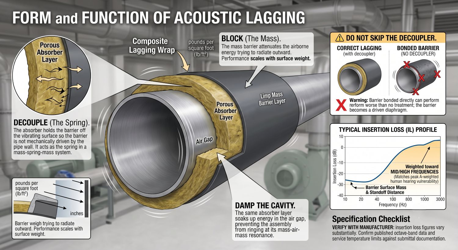
Acoustic lagging is a composite wrap applied directly to a noise-radiating surface – process piping, ductwork, valves, blower housings, hoppers, chutes – consisting of a porous absorber layer against the substrate and a limp mass barrier layer on the outside. The two layers do different jobs, and the order matters.
- Decouple. The absorber holds the barrier off the vibrating surface so the barrier is not mechanically driven by the pipe wall. It is the spring in a mass-spring-mass system.
- Block. The mass barrier attenuates the airborne energy trying to radiate outward. Performance scales with surface weight, which is why barrier products are specified in pounds per square foot rather than inches.
- Damp the cavity. The same absorber layer soaks up energy in the air gap between substrate and barrier, keeping the assembly from ringing at its mass-air-mass resonance.
|
Do not skip the decoupler. A barrier bonded directly to a hot or vibrating surface can perform worse than no treatment at all in certain frequency bands, because the barrier becomes a driven diaphragm. The absorber is not padding – it is a functional part of the system. Verify with the manufacturer: insertion loss figures for lagging assemblies vary substantially by barrier weight, absorber thickness, standoff, and frequency. Confirm published octave-band data and service temperature limits against submittal documentation before specifying. |
A properly built lagging assembly typically delivers meaningful insertion loss weighted toward mid and high frequencies, with low-frequency performance determined by barrier surface mass and standoff distance. That frequency profile matters: mid and high frequencies are exactly where A-weighting puts its emphasis, and exactly where human hearing is most vulnerable.
Where do the decibels actually come from? A worked example
Consider a packaging line operator in a hard-surfaced plant. Baseline personal dosimetry returns 93 dBA as an 8-hour TWA. The dominant contributor at the operator's ear is a run of compressed-air and blower piping directly overhead; the remainder is reverberant field from the production floor as a whole.
|
Baseline |
After lagging the overhead piping |
After lagging + added room absorption |
|
|---|---|---|---|
|
8-hour TWA |
93 dBA |
88 dBA |
84 dBA |
|
Permitted duration (Table G-16) |
5.3 hours |
10.6 hours |
18.4 hours |
|
Noise dose |
152% |
76% |
44% |
|
Compliance position |
Above the PEL – feasible controls required |
Below the PEL, above the action level – hearing conservation program continues |
Below the action level – program no longer triggered by this exposure |
Dose is calculated as D = 100 × (C ÷ T), where C is actual exposure time and T is the permitted duration from Table G-16, given by T = 8 ÷ 2^((L − 90) ÷ 5).
|
Why the second step is the whole point. Lagging removes the dominant direct path. Once that path is gone, what remains at the operator's ear is the reverberant field – and no additional source treatment touches it. That residual is the noise floor. Lowering it requires adding absorption to the room itself. Reverberant level falls by 10 × log(A₂ ÷ A₁), so doubling the total absorption in a space yields about 3 dB. The 4 dB in the final column comes from roughly two-and-a-half times the baseline absorption – achievable in a bare-deck plant with hanging baffles or ceiling and wall panels, and essentially unachievable by treating machines one at a time. |
Which acoustic product solves which problem?
Matching the product to the transmission path is most of the work. The Insulation Guy stocks the full range, and the selection logic is straightforward once the path is identified.
|
If the noise is… |
The path is… |
Specify… |
|---|---|---|
|
Radiating from pipe, duct, valve, or blower housing |
Structure-borne, converting to airborne at the surface |
Acoustic lagging – quilted fiberglass with a barrier septum or barrier backing |
|
Building up across a hard-surfaced bay with no single dominant source |
Reverberant |
Hanging baffles, ceiling and wall absorption panels |
|
Traveling from one work area into an adjacent one |
Airborne, across open space |
Acoustic curtain systems or barrier wall panels |
|
Escaping a machine you can surround |
Airborne, near-field |
Curtain enclosure – absorptive face inward, barrier face outward |
|
At the operator station on equipment that cannot be wrapped or enclosed |
Direct field |
Free-standing barrier partition with an absorptive face toward the source |
Two quilted fiberglass configurations, and when to use each
- Barrier Septum Composite ("BSC" style) – absorber / barrier / absorber sandwich. It absorbs on both faces while blocking through the middle. Use where both sides of the assembly face occupied space, such as an aisle-side machine curtain in a working bay.
- Barrier-backed – absorber on the source side, mass barrier on the outboard face. Use for pipe and duct lagging and for enclosure walls where only one face is exposed to the noise.
Product detail: Quilted Fiberglass Sound Absorption · Full line: Acoustic Insulation Solutions
What to gather before you specify
Most lagging projects underperform because the specification was written from a single dBA number. Bring the following to the conversation:
- Personal dosimetry TWAs by job classification – not just area sound level readings. Compliance follows the worker, not the location.
- Octave-band data at the source. A single A-weighted number cannot tell you whether the problem calls for mass or for thickness.
- Substrate surface temperature, both normal operating and upset conditions.
- Removability requirements. Lagging over insulated process piping usually needs to come off for inspection, which drives closure and jacketing selection.
- Flame spread and smoke developed requirements – ASTM E84 Class A where applicable.
- Washdown, chemical exposure, or food-contact area conditions, which drive facing material selection.
- Corrosion under insulation (CUI) risk on the substrate. Adding a wrap to a hot or cyclically wet line changes the moisture picture – evaluate CUI exposure alongside the acoustic goal.
- Penetration count – valves, flanges, hangers, supports. This is where lagging jobs leak, and it is almost always undercounted at quoting.
Five mistakes that keep facilities stuck above 85 dBA
- Buying NRC when the problem needed STC. An absorber cannot block a transmission path, however good its absorption coefficient.
- Lagging the straight run and leaving the fittings bare. Acoustic leaks dominate an assembly. Roughly 1% open area caps the effective transmission loss of a barrier at about 20 dB, no matter how heavy the barrier is.
- Treating the room when the worker stands in the direct field. Absorption panels do nothing for an operator three feet from the source. That exposure requires source treatment or a barrier between source and ear.
- Chasing dBA totals without octave-band data. Two workstations at 92 dBA can require completely different treatments if one is dominated by 250 Hz and the other by 2 kHz.
- Assuming PPE closes the gap on paper. Derate the NRR, account for real-world wear time, and the protected exposure is usually well above what the spec sheet suggested.
Frequently asked questions
What is acoustic lagging?
Acoustic lagging is a composite wrap applied directly to a noise-radiating surface such as a pipe, duct, valve, or blower housing. It combines a porous absorber layer against the substrate with a limp mass barrier layer on the outside. The absorber decouples the barrier from the vibrating surface; the barrier provides the transmission loss.
Does acoustic lagging help with OSHA compliance?
Yes. Acoustic lagging is an engineering control – it reduces noise at the source rather than at the worker's ear. Under 29 CFR 1910.95(b)(1), feasible engineering or administrative controls must be used when exposures exceed the limits in Table G-16, with hearing protection supplementing rather than replacing those controls.
What is the difference between NRC and STC?
NRC (Noise Reduction Coefficient) measures how much sound a material absorbs, on a scale from 0.00 to just above 1.00. STC (Sound Transmission Class) measures how much sound a material blocks from passing through, expressed in decibels. A material can score high on one and near zero on the other; they are separate mechanisms.
What is OSHA's noise action level?
OSHA's action level is 85 dBA as an 8-hour time-weighted average. At or above it, an employer must run a hearing conservation program: exposure monitoring, baseline and annual audiometric testing, hearing protectors available at no cost, annual training, and recordkeeping. The separate permissible exposure limit is 90 dBA as an 8-hour TWA.
Can hearing protection alone satisfy OSHA's noise standard?
Not where engineering or administrative controls are feasible. The standard establishes controls as the primary means of reducing exposure and treats protective equipment as a supplement. In practice, rated attenuation also overstates field performance – OSHA's own method subtracts 7 dB from the NRR for A-weighted measurements and directs an additional 50% derating when assessing adequacy.
Why doesn't quieting the loudest machine fix the problem?
Because sound sources add logarithmically. Ten equal sources produce a level 10 dB higher than one; silencing one of the ten lowers the total by roughly 0.5 dB. Beyond the critical distance from any single machine, a worker is hearing the reverberant field of the whole room rather than any individual source.
Will adding absorption alone lower the noise floor?
It will lower the reverberant portion, which is the floor itself – reverberant level drops by 10 × log of the ratio of new to old total absorption, so doubling absorption yields about 3 dB. It will not help a worker positioned in the direct field close to a source. Most facilities need source treatment and room absorption together.
How is a noise dose calculated?
Dose equals 100 × (C ÷ T), where C is actual hours of exposure at a given level and T is the permitted duration for that level from Table G-16, calculated as T = 8 ÷ 2^((L − 90) ÷ 5). Mixed exposures are summed across levels. A dose above 100% exceeds the permissible exposure limit.
|
Bring us the dosimetry, not just the decibel number. The Insulation Guy distributes the full acoustic range – quilted fiberglass absorbers, barrier septum and barrier-backed composites, hanging baffles, acoustic curtains, and barrier wall systems – nationwide, and helps facility and EHS teams match the product to the transmission path rather than to a catalog page. Send the octave-band data and the affected job classifications, and we will help you build a specification that closes the gap between your current exposures and the requirements of 1910.95. |